29Jan
How to Using a Multimeter in a Computer Troubleshooting ( PC )
How to Using a Multimeter in a Computer Troubleshooting ( PC )
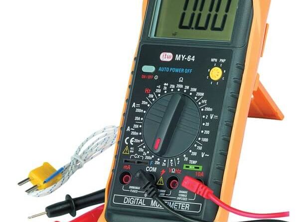
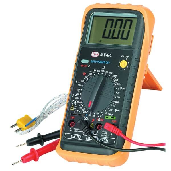
Many types of test instruments can help you isolate computer hardware problems. The most basic pieces of electronic troubleshooting equipment is the multimeter. These test instruments are available in both analog and digital figure and can be used to directly measure electrical values of voltage symbol is (V), current in milliamperes symbol is (mA) or amperes symbol is (A), and resistance in ohms. Therefore, these devices are referred to as VOMs (volt-ohmmilliammeters) for analog types, or DMMs (digital multimeters) for digital types.
A digital multimeter. You can use this device to check the following:
- · diodes,
- · transistors,
- · capacitors,
- · motor windings,
- · relays, and coils.
This particular point of DMM contains facilities built in to the meter to test transistors and diodes. These facilities are in addition to its standard functions of current, voltage, and resistance measurement; however, in computer repair work, only the voltage and resistance functions are used extensively.
The first step in using the multimeter to perform tests is to select the proper function. For the most part, you never need to use the current function of the multimeter when working with computer systems;
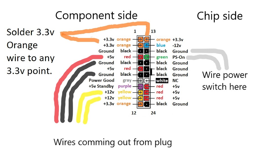
In computer troubleshooting, most of the tests are DC voltage readings.
These measurements usually involve checking the DC side of the powersupply unit. You can make these readings between ground and one of the expansion-slot pins, or at the system board power-supply connector. The voltage across most of the capacitors on the system board is 5V (DC). The DC voltages that can normally be expected in a PC-compatible system are +12V, +5V, –5V, and –12V. The actual values for these readings might vary by 5% in whichever direction. The DC voltage function is used to take measurements in live DC circuits.
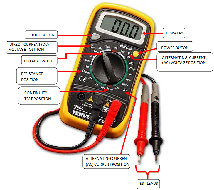
It should be connected in parallel with the device being checked. This could mean connecting the reference lead (black lead) to a ground point and the measuring lead (red lead) to a test point to take a measurement, as the following picture for reference.
As an estimated value is detected, you can decrease the range setting to realize a more accurate sense. Most meters allow for overvoltage protection.
Malfunction to turn off the power when making resistance checks can cause serious damage to the meter and can pose a possible risk to the technician. Resistance checks require that you electrically isolate the element being tested from the system. For the most circuit components, this means desoldering at least one end from the circuit board. The resistance check is very useful in isolating some types of problems in the system. One of the main uses of the resistance function is to test fuses. You must disconnect at least one end of the fuse from the system.
You should be set the meter on the 1k ohm resistance setting in the multimeter.
- · If the fuse is good, the meter should read near 0 value ohms. If fuse is bad, the meter reads unlimited.
- · The resistance function also is useful in checking for cables and connectors.
- · By removing the cable from the system and connecting a meter lead to each end, you can check the cable’s continuity conductor by conductor to verify its reliability.
- · You also use the resistance function to test the system’s of speaker.
· To check the speaker, simply disconnect the speaker from the system and connect a meter lead to each end.
o In case If the speaker is good, the meter should read near 8 ohms (although a smaller speaker might be 4 ohms).
o In case If the speaker is defective, the resistance reading should be 0 for shorts or infinite for opens.
o Only a couple of situations involve using the AC voltage function for checking microcomputer systems.
The primary use of this function is to check the commercial power being applied to the power-supply unit. As with any measurement, it is important to select the correct measurement range; however, the fatal voltage levels associated with the power supply call for additional caution when making such measurements.
The second application for the AC voltage function is to measure ripple voltage from the DC output side of the power-supply unit. This particular operation is very rarely performed in field-service situations.


Leave a Reply